Features
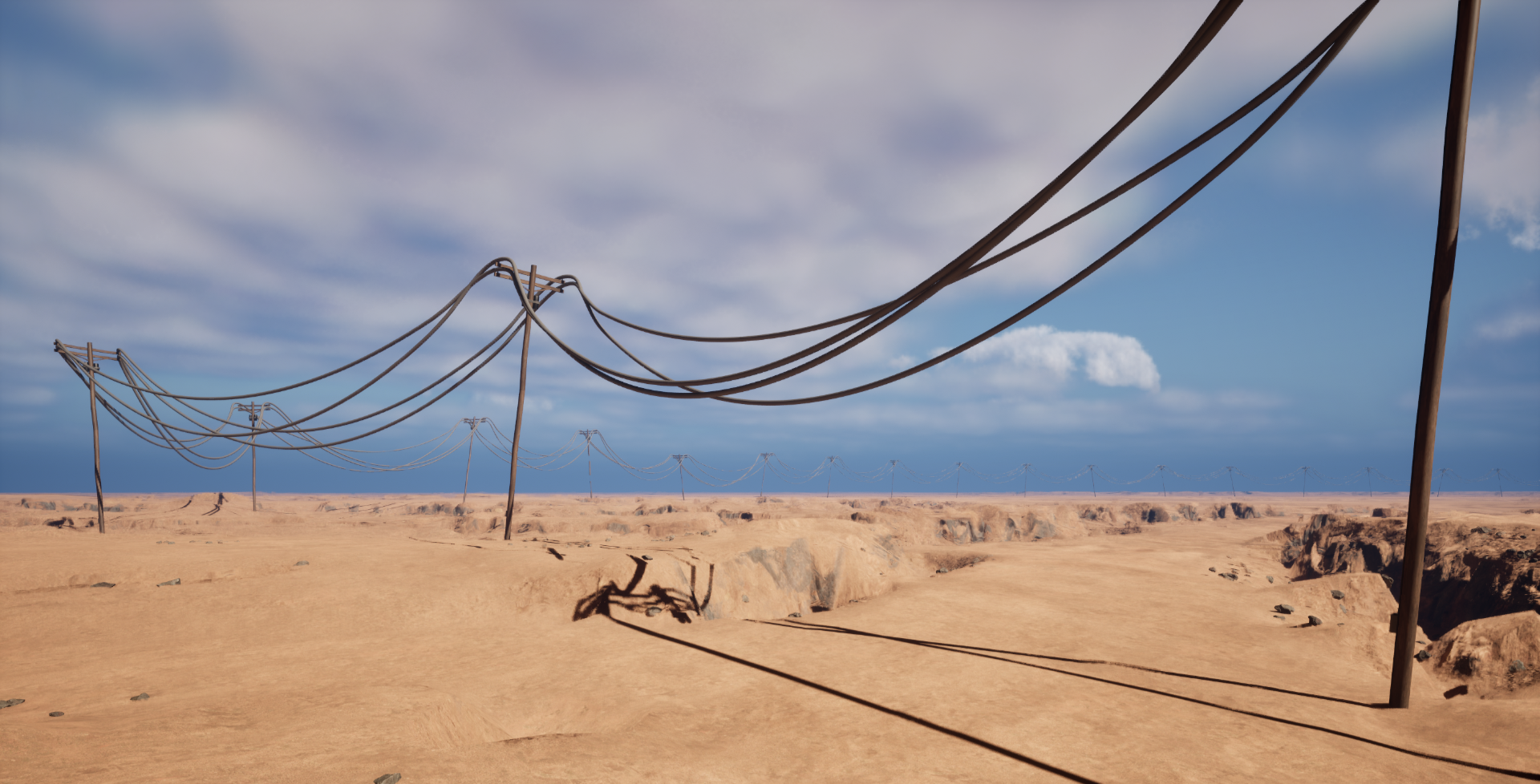
- Performant power lines procedural generation
- Acurate paralel catenary calculation
- Class preset based construction
- Randomization
- Terrain snaping
Prerequisites
Installation
The plugin can be adquired in Fab or cloned or downloaded for free from GitHub.
If you got Git installed on your computer you can clone the repository by typing this command in a terminal in your project “Plugins” folder:
1
git clone https://github.com/Bumvolla/UE_EasyPowerLines.git
or, if you already got your unreal project in a git repository:
1
git submodule add https://github.com/Bumvolla/UE_EasyPowerLines.git
If not, you can download the .zip file in the latest release and extract it in your project “Plugins” folder
In engine
For this plugin to work you’ll need:
- An static mesh for the pole
- An static mesh for the wire
- Setup a blueprint that inherits from Catenary pole preset
You have examples for all of them in the Plugin content folder.
Catenary pole preset
Blueprint creation
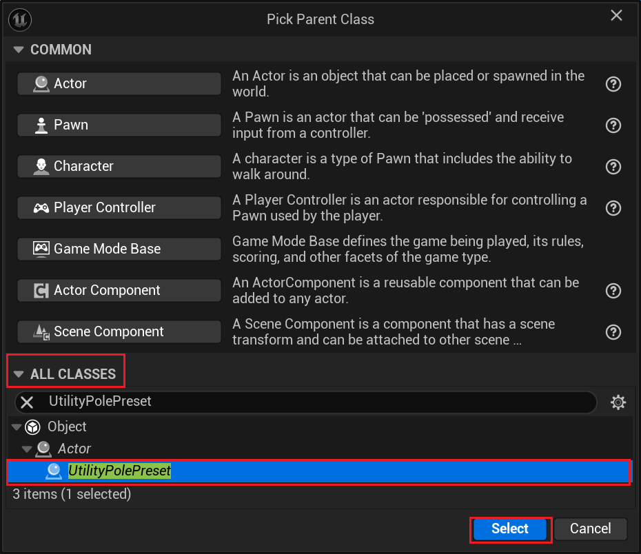
- Right click in the content browser.
- Select create basic asset -> Blueprint class
- Open the All classes dropdown and search for UtilityPolePreset
- Press the select button.
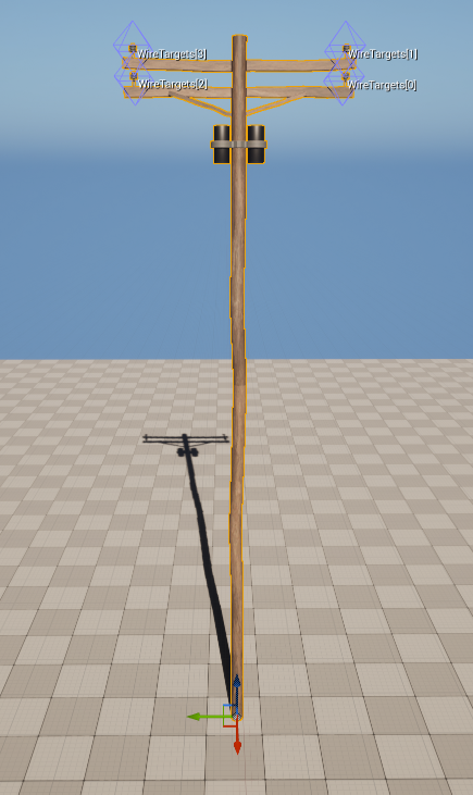
Blueprint setup
- Drag and drop the blueprint in the scene.
- In the details panel, fill the values:
- Pole mesh : The static mesh that the pole will have.
- Wire targets : Add as many items to the array as connections the pole will have, then move each one of the widgets to the positions where the connections will be.
- Press the Copy to class defaults button in the details pannel.
- Make sure the values have refreshed inside the blueprint, if not, they will once the editor is restarted.
Plugin usage
Point to point catenary
- Open the Place actor window in the editor and search for: Point to point, drag and drop it to the scene.
- Place both position widgets in the desired place.
- Fill the parameters.
- Press the Generate button.

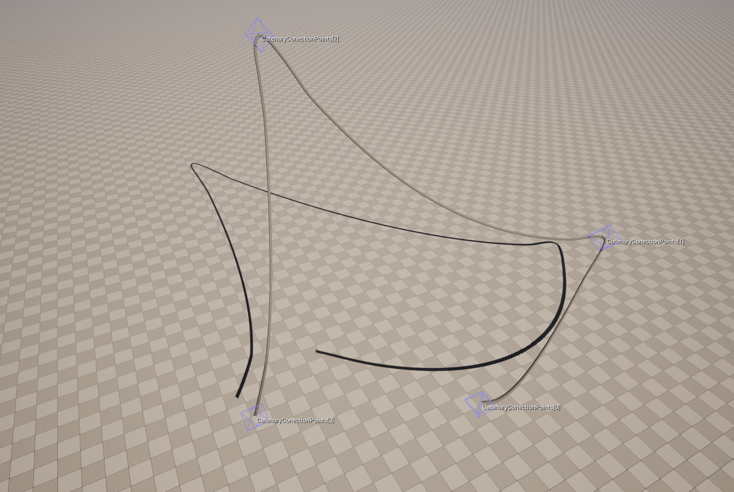
Multiple point catenary
- Open the Place actor window in the editor and search for: Multiple point catenary, drag and drop it to the scene.
- Add as many position widgets as desired and place them in the scene in the desired place.
- Fill the parameters.
- Press the Generate button.
Utility pole
- Open the Place actor window in the editor and search for: Utility pole, drag and drop it to the scene.
- Place the actor where desired.
- Fill the parameters.
- Press the Generate button.
IMPORTANT:Remember to fill out the ‘‘ACTOR TO CONECT TO’’ parameter.
Spline utility pole
- Open the Place actor window in the editor and search for: Spline utility pole, drag and drop it to the scene.
- Shape the spline however you want.
- Fill the parameters.
- Press the Generate button.
Parameter description
General parameters
| Param | Description |
|---|---|
| Slack | The min ammount of slack the wires will have |
| Slack variation | Max random ammount of slack that will be added to the slack value |
| Spline resolution | Determines how defined the catenary curve will be (Very high values will hit performance) |
| Wire mesh | Static mesh that will be used for the wire generation |
| Wire mesh axis | The axis of the static mesh that will be the connection point, usually the long one |
| Auto generate | Determines if the logic runs or not in the construction script (beta) |
| Cleanup splines | When true will cleanup the wire splines after finishing the process |
Pole based generation parameters
| Param | Description |
|---|---|
| Preset class | Utility pole preset child class that will define pole mesh and wire conection targets |
| Random tilt | Max random rotation that will be applied to the poles |
| Snap to terrain | Determines if the poles will try or not snap themselves to the terrain height |
| Ray length | Determines the distance the raycast will check while trying to find nearest terrain |
| Align to normal | Determines whether the pole will align to the raycast hit normal or not |
| Collision channel | Collision channel the raycast will test for collision |
| Draw debug lines | Determines if debug lines will be drawn for the raycast |
Specific parameters
Utility Pole
| Param | Description |
|---|---|
| Actor to conect to | The utility pole that will be used to create the splines from the one you’re filling |
Spline utility pole
| Param | Description |
|---|---|
| Is closed loop | Determines if the spline is or not a closed loop |
| Distance between objects | The distance, in centimeters, between each of the poles that will be generated. |
Parameters details
Draw debug lines
Draw debug lines will draw for 10 seconds 3 lines from diferent colors:
- A red line that shows the actual raycast path.
- A green line that displays the first raycast collision point.
- A blue line coming from the impact location to the direction the normal is pointing to.
Cleanup splines
Cleanup splines exist because of the impact on the viewport performance of large splines with a lot of points while the “game view”(G shortcut) is turned off.
Having it turned off is usefull for visualization purposes and reduces the overall generation process speed. The idea is turning it on once you’re done with the tool setup.